A Comprehensive Guide to Karnaugh Maps: Simplifying Boolean Expressions for Efficient Circuit Design
Related Articles: A Comprehensive Guide to Karnaugh Maps: Simplifying Boolean Expressions for Efficient Circuit Design
Introduction
With enthusiasm, let’s navigate through the intriguing topic related to A Comprehensive Guide to Karnaugh Maps: Simplifying Boolean Expressions for Efficient Circuit Design. Let’s weave interesting information and offer fresh perspectives to the readers.
Table of Content
- 1 Related Articles: A Comprehensive Guide to Karnaugh Maps: Simplifying Boolean Expressions for Efficient Circuit Design
- 2 Introduction
- 3 A Comprehensive Guide to Karnaugh Maps: Simplifying Boolean Expressions for Efficient Circuit Design
- 3.1 Understanding the Basics of K-maps
- 3.2 Constructing a K-map: A Step-by-Step Approach
- 3.3 Illustrative Example: Simplifying a Boolean Function
- 3.4 Benefits of Using K-maps in Digital Logic Design
- 3.5 Frequently Asked Questions (FAQs) about K-maps
- 3.6 Tips for Efficiently Using K-maps
- 3.7 Conclusion
- 4 Closure
A Comprehensive Guide to Karnaugh Maps: Simplifying Boolean Expressions for Efficient Circuit Design

Karnaugh maps, often referred to as K-maps, are a powerful visual tool used in digital logic design to simplify Boolean expressions. They provide a systematic approach to minimizing logical functions, leading to simpler, more efficient, and cost-effective digital circuits. This article delves into the intricacies of K-maps, explaining their underlying principles, practical applications, and the significant benefits they offer in the realm of digital circuit design.
Understanding the Basics of K-maps
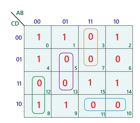
At their core, K-maps are a graphical representation of truth tables, visually organizing the output values of a Boolean function based on the various combinations of input variables. Each cell in a K-map corresponds to a unique combination of input values, and the value within the cell represents the output of the function for that specific input combination.
Key Features of K-maps:
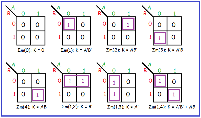
- Grid Structure: K-maps are structured as a grid, with the number of rows and columns determined by the number of input variables. For example, a function with two input variables would require a 2×2 grid, while a function with three variables would utilize a 2×4 grid.
- Adjacent Cells: Adjacent cells in a K-map represent input combinations that differ by only one variable. This adjacency is crucial for simplification, as it allows for the grouping of adjacent cells with the same output value.
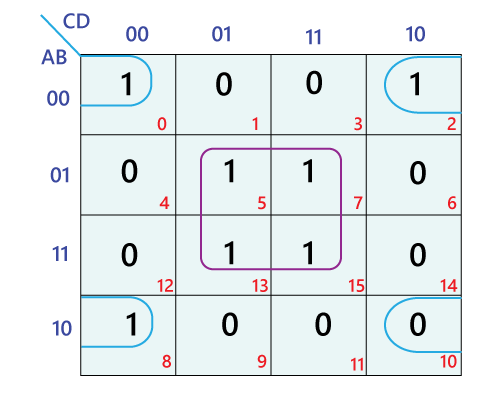
- Gray Code Ordering: The rows and columns of a K-map are arranged in Gray code order, ensuring that adjacent cells always differ by a single bit. This arrangement facilitates the identification of adjacent groups of cells.
- Grouping for Simplification: The primary objective of using K-maps is to identify and group adjacent cells containing ‘1’s, representing the function’s output for those specific input combinations. These groups form ‘implicants,’ which represent simplified terms in the Boolean expression.
Constructing a K-map: A Step-by-Step Approach
-
Determine the Number of Input Variables: The number of input variables dictates the size and structure of the K-map. For example, a function with three input variables (A, B, C) requires a 2×4 grid.
-
Label the Rows and Columns: The rows and columns are labeled according to the Gray code representation of the input variables. For a 2×4 K-map, the rows would be labeled as 00, 01, 11, and 10, while the columns would be labeled as A, B, C.
-
Fill in the Cells: Each cell in the K-map corresponds to a specific combination of input values. The output value of the function for that combination is entered into the respective cell.
-
Identify and Group Adjacent Cells: Look for adjacent cells containing ‘1’s and group them together. The groups should be as large as possible, covering the maximum number of ‘1’s.
-
Write the Simplified Boolean Expression: Each group of adjacent cells represents a simplified term in the Boolean expression. The term is formed by identifying the input variables that remain constant within the group.
Illustrative Example: Simplifying a Boolean Function
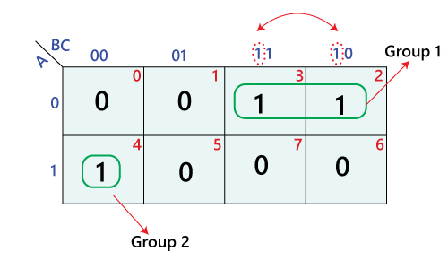
Consider the Boolean function: F(A, B, C) = Σm(0, 1, 2, 4, 6)
-
Construct the K-map: A 2×4 K-map is required for three input variables. The rows are labeled 00, 01, 11, 10, and the columns are labeled A, B, C.
-
Fill in the Cells: The cells corresponding to minterms 0, 1, 2, 4, and 6 are filled with ‘1’s, while the remaining cells are filled with ‘0’s.
-
Identify Groups: Two groups can be formed:
- Group 1: Cells 0, 1, 4, 5, representing the term A’C.
- Group 2: Cells 0, 2, 4, 6, representing the term BC’.
-
Simplified Expression: The simplified Boolean expression is F(A, B, C) = A’C + BC’.
Benefits of Using K-maps in Digital Logic Design
-
Simplified Boolean Expressions: K-maps enable the efficient simplification of Boolean expressions, leading to more compact and efficient logic circuits.
-
Reduced Circuit Complexity: By minimizing the number of logic gates required, K-maps contribute to simpler and less complex circuit designs.
-
Cost Optimization: Simplified circuits translate to fewer components and lower production costs.
-
Improved Performance: Minimizing logic gates reduces propagation delays and improves the overall performance of digital circuits.
-
Enhanced Readability and Maintainability: K-maps provide a clear and visually intuitive representation of Boolean functions, making it easier to understand, modify, and maintain circuit designs.
Frequently Asked Questions (FAQs) about K-maps
Q1: What is the maximum number of variables that can be represented by a K-map?
A: The maximum number of variables that can be represented by a K-map is determined by the size of the grid. For practical purposes, K-maps are typically limited to 5 or 6 variables, as larger maps become increasingly complex and difficult to manage.
Q2: How do I handle "don’t care" conditions in K-maps?
A: "Don’t care" conditions, denoted by ‘X’ in the K-map, represent input combinations for which the output value is irrelevant. These conditions can be utilized to simplify the Boolean expression by including them in groups if it leads to a larger and more simplified term.
Q3: What are some common errors to avoid when using K-maps?
A: Common errors include:
- Incorrect Gray Code Ordering: Ensure that the rows and columns are arranged in Gray code order to maintain adjacency between relevant cells.
- Incomplete Grouping: Aim to form the largest possible groups of adjacent cells containing ‘1’s to achieve maximum simplification.
- Overlapping Groups: Avoid overlapping groups, as each group represents a distinct term in the simplified expression.
Q4: Are there any limitations to using K-maps?
A: While K-maps are a powerful tool, they do have some limitations:
- Limited Scalability: As the number of input variables increases, K-maps become increasingly complex and difficult to manage.
- Complexity of Multi-Output Functions: K-maps are less effective for simplifying multi-output functions, where multiple outputs are dependent on the same set of input variables.
Tips for Efficiently Using K-maps
-
Start with a Clear Truth Table: Begin by constructing a complete truth table for the Boolean function.
-
Organize the K-map Properly: Ensure that the rows and columns are labeled correctly in Gray code order.
-
Group Cells Strategically: Aim to form the largest possible groups of adjacent cells, even if it means including "don’t care" conditions.
-
Verify the Simplified Expression: After obtaining the simplified expression, verify its accuracy by comparing it to the original truth table.
-
Practice Regularly: Consistent practice with K-maps is crucial to develop proficiency and confidence in using this valuable tool.
Conclusion
Karnaugh maps provide a visual and systematic approach to simplifying Boolean expressions, leading to more efficient and cost-effective digital circuit designs. By understanding the principles of K-maps and following the steps outlined in this guide, designers can leverage this tool to create optimized circuits with reduced complexity and improved performance. While K-maps have limitations, they remain an indispensable tool in the arsenal of digital logic designers, facilitating the creation of robust and efficient digital systems.


Closure
Thus, we hope this article has provided valuable insights into A Comprehensive Guide to Karnaugh Maps: Simplifying Boolean Expressions for Efficient Circuit Design. We thank you for taking the time to read this article. See you in our next article!