Karnaugh Maps: A Visual Approach to Digital Logic Design
Related Articles: Karnaugh Maps: A Visual Approach to Digital Logic Design
Introduction
In this auspicious occasion, we are delighted to delve into the intriguing topic related to Karnaugh Maps: A Visual Approach to Digital Logic Design. Let’s weave interesting information and offer fresh perspectives to the readers.
Table of Content
Karnaugh Maps: A Visual Approach to Digital Logic Design

Introduction
In the realm of digital logic design, the efficient implementation of Boolean functions is paramount. This involves minimizing the number of logic gates required, thereby reducing circuit complexity, cost, and power consumption. Karnaugh maps (K-maps), a graphical method for simplifying Boolean expressions, provide a powerful and intuitive approach to achieving this optimization.
Understanding Karnaugh Maps
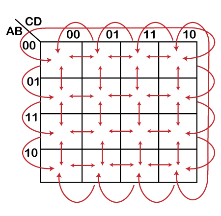
A Karnaugh map is a visual representation of a truth table, where each cell corresponds to a unique combination of input variables. The arrangement of cells is not arbitrary but follows a specific pattern designed to facilitate the identification of adjacent cells representing minterms (product terms) that differ by only one variable. This adjacency, even when physically separated on the map, is crucial for simplifying Boolean expressions.
Construction of a Karnaugh Map
The construction of a K-map involves the following steps:
-
Determine the number of variables: The number of input variables dictates the size of the K-map. For ‘n’ variables, a 2^n cell map is required. For example, a 2-variable function needs a 2^2 = 4-cell map, while a 3-variable function requires a 2^3 = 8-cell map.
-
Label the rows and columns: The rows and columns of the K-map are labeled with binary combinations of input variables, ensuring Gray code ordering. Gray code is a binary code where successive values differ by only one bit, allowing for easy identification of adjacent cells.
-
Populate the cells: Each cell in the K-map represents a unique combination of input variables. The cell’s value is determined by the output of the Boolean function for that specific input combination, typically represented by a ‘1’ for a true output and a ‘0’ for a false output.
Simplifying Boolean Expressions with K-maps
The core strength of K-maps lies in their ability to simplify Boolean expressions by identifying groups of adjacent cells containing ‘1’s. These groups represent minterms that can be combined to form simplified product terms. The simplification process follows these steps:
-
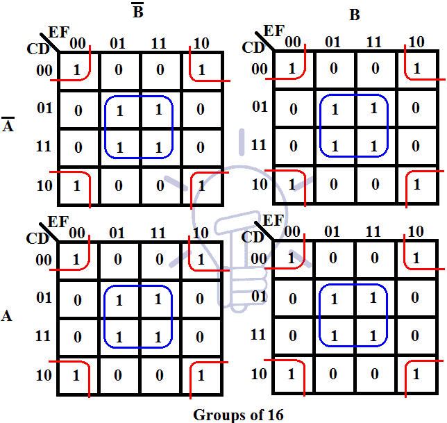
Identify groups of adjacent ‘1’s: Look for groups of ‘1’s that are adjacent horizontally, vertically, or diagonally. Each group must contain a power of two number of cells (1, 2, 4, 8, etc.).
-
Form simplified product terms: For each group, identify the input variables that remain constant within the group. These variables form the product term corresponding to that group.
-
Combine the simplified terms: The final simplified Boolean expression is the sum of the product terms obtained from each group.
Illustrative Example
Consider the following Boolean expression:
F(A, B, C) = Σ(0, 1, 2, 3, 5, 6)This expression represents a function with three input variables (A, B, C) and outputs a ‘1’ for the input combinations 0, 1, 2, 3, 5, and 6.
Constructing the K-map:
-
Number of variables: 3 variables (A, B, C) require a 2^3 = 8-cell map.
-
Labeling: Rows are labeled with binary combinations of B and C, while columns are labeled with A, all in Gray code order.
-
Population: The cells corresponding to input combinations 0, 1, 2, 3, 5, and 6 are marked with ‘1’, while the rest are marked with ‘0’.
Simplifying the expression:
-
Identify groups: Two groups are identified: a group of four ‘1’s (representing the minterms 0, 1, 2, and 3) and a group of two ‘1’s (representing the minterms 5 and 6).
-
Form simplified terms: The group of four represents the product term ‘B’ (as B is constant within the group), while the group of two represents the product term ‘A’ ‘C’.
-
Combine the terms: The simplified expression is:
F(A, B, C) = B + A'CAdvantages of Karnaugh Maps
-
Visual Simplification: K-maps provide a visual representation of the Boolean expression, making it easier to identify and combine adjacent minterms.
-
Intuitive Approach: The graphical nature of K-maps allows for an intuitive understanding of the simplification process.
-
Systematic Method: K-maps offer a systematic method for minimizing Boolean expressions, ensuring that all possible simplifications are considered.
-
Easy Handling of Don’t Care Conditions: K-maps can easily accommodate don’t care conditions, where the output of the function is irrelevant for certain input combinations. These conditions can be used to further simplify the expression.
Applications of Karnaugh Maps
K-maps find widespread application in digital logic design, including:
-
Logic Circuit Optimization: K-maps are used to simplify Boolean expressions, resulting in more efficient logic circuits with fewer gates and reduced complexity.
-
Digital System Design: K-maps are crucial for designing digital systems, such as adders, subtractors, multiplexers, and decoders.
-
Fault Detection and Diagnosis: K-maps can be used to analyze logic circuits for potential faults and to diagnose issues in existing designs.
-
Educational Tool: K-maps are widely used as an educational tool to teach the fundamentals of Boolean algebra and logic circuit design.
FAQs about Karnaugh Maps
Q1: What is the maximum number of variables that can be handled by a K-map?
A: While K-maps are a powerful tool, their practicality diminishes for functions with a large number of variables. The size of the map grows exponentially with the number of variables. For example, a 5-variable function requires a 2^5 = 32-cell map, which becomes increasingly difficult to visualize and manipulate. Beyond 5-6 variables, alternative simplification methods like Quine-McCluskey algorithm are preferred.
Q2: How do K-maps handle don’t care conditions?
A: Don’t care conditions, denoted by ‘X’ in the K-map, represent input combinations where the output of the function is irrelevant. During simplification, these cells can be included in any group to achieve further simplification, as their output value has no effect on the final result.
Q3: Can K-maps be used for functions with multiple outputs?
A: Yes, K-maps can be used for functions with multiple outputs. A separate K-map is constructed for each output, and the simplification process is applied independently to each map.
Q4: Are there any limitations of Karnaugh maps?
A: While K-maps are a powerful tool, they have certain limitations:
-
Limited to a small number of variables: As mentioned earlier, K-maps become cumbersome for functions with more than 5-6 variables.
-
Manual process: Simplification with K-maps is a manual process, potentially prone to errors, especially for larger maps.
-
Limited to specific Boolean expressions: K-maps are best suited for simplifying sum-of-products (SOP) expressions. For other forms, like product-of-sums (POS), additional transformations may be required.
Tips for Using Karnaugh Maps
-
Start with a clear truth table: Ensure that the truth table for the function is accurate and complete before constructing the K-map.
-
Use Gray code labeling: Always label the rows and columns of the K-map using Gray code to ensure that adjacent cells differ by only one bit.
-
Look for the largest groups first: Begin by identifying the largest groups of adjacent ‘1’s, as these will contribute the most to simplification.
-
Don’t overlook diagonal adjacency: Remember that cells can be adjacent diagonally, especially in larger K-maps.
-
Use don’t care conditions strategically: Include don’t care conditions in groups to achieve maximum simplification.
Conclusion
Karnaugh maps provide a powerful and intuitive approach to simplifying Boolean expressions in digital logic design. Their graphical representation allows for easy identification of adjacent minterms, leading to optimized logic circuits with reduced complexity and cost. While K-maps have limitations for functions with a large number of variables, they remain a valuable tool for simplifying logic expressions and understanding the fundamentals of digital logic design. Their visual nature makes them an excellent educational tool, fostering a deeper understanding of Boolean algebra and its applications in the realm of digital circuits.


Closure
Thus, we hope this article has provided valuable insights into Karnaugh Maps: A Visual Approach to Digital Logic Design. We hope you find this article informative and beneficial. See you in our next article!