The Karnaugh Map: A Visual Tool for Simplifying Boolean Expressions in Digital Electronics
Related Articles: The Karnaugh Map: A Visual Tool for Simplifying Boolean Expressions in Digital Electronics
Introduction
With great pleasure, we will explore the intriguing topic related to The Karnaugh Map: A Visual Tool for Simplifying Boolean Expressions in Digital Electronics. Let’s weave interesting information and offer fresh perspectives to the readers.
Table of Content
- 1 Related Articles: The Karnaugh Map: A Visual Tool for Simplifying Boolean Expressions in Digital Electronics
- 2 Introduction
- 3 The Karnaugh Map: A Visual Tool for Simplifying Boolean Expressions in Digital Electronics
- 3.1 Understanding the Karnaugh Map
- 3.2 Constructing a Karnaugh Map
- 3.3 Simplifying Boolean Expressions with K-Maps
- 3.4 Advantages of Using Karnaugh Maps
- 3.5 Examples of K-Map Applications
- 3.6 FAQs about Karnaugh Maps
- 3.7 Tips for Using Karnaugh Maps
- 3.8 Conclusion
- 4 Closure
The Karnaugh Map: A Visual Tool for Simplifying Boolean Expressions in Digital Electronics

The realm of digital electronics revolves around manipulating binary information. At its core lies the concept of Boolean algebra, a system for representing and manipulating logical relationships using operators like AND, OR, and NOT. Boolean expressions, formed by combining these operators with variables, represent the logic of digital circuits. However, these expressions can become complex and difficult to understand, especially for circuits with many inputs. This is where the Karnaugh map (K-map) emerges as a powerful tool, simplifying Boolean expressions and offering a visual approach to designing efficient digital circuits.
Understanding the Karnaugh Map
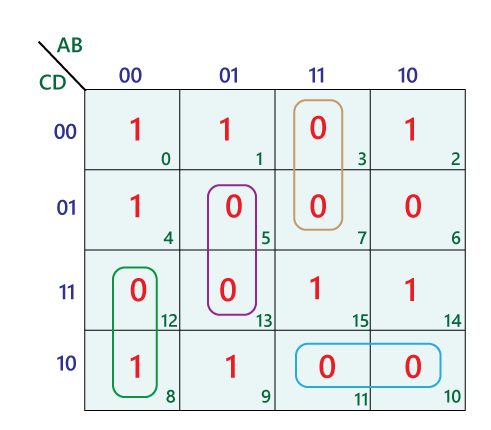
A Karnaugh map is a graphical representation of a truth table, a tabular representation of all possible input combinations and their corresponding output values for a logic function. Unlike a truth table, the K-map arranges the input combinations in a specific way, ensuring adjacent cells represent input combinations differing by only a single bit. This arrangement allows for easy identification of groups of ‘1’s (representing "true" output) that can be combined to simplify the Boolean expression.
Constructing a Karnaugh Map
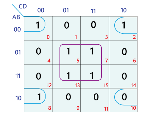
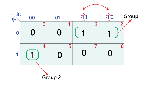
The construction of a K-map depends on the number of input variables. For a two-variable function, a 2×2 grid is used, with each cell representing a unique combination of the two inputs. For three variables, a 2×4 grid is employed, and for four variables, a 4×4 grid. The arrangement of cells within the grid is crucial, ensuring adjacent cells differ by only a single input variable. This arrangement is achieved by using a Gray code sequence, where each subsequent code differs by only one bit.
Simplifying Boolean Expressions with K-Maps
The core advantage of the K-map lies in its ability to visually simplify Boolean expressions. Once the output values are mapped onto the K-map, the simplification process involves identifying groups of adjacent ‘1’s. These groups can be of any size, as long as they are rectangular and contain a power of two number of cells (1, 2, 4, 8, etc.). Each group represents a simplified product term in the Boolean expression.
The following rules guide the simplification process:
- Larger groups are preferred: A group of four ‘1’s will result in a simpler term than two groups of two ‘1’s.
- All ‘1’s must be included: Every ‘1’ on the map must be included in at least one group.
- Overlap is allowed: Groups can overlap, and overlapping ‘1’s can be used to form multiple groups.
- Wrap-around is possible: In a K-map, the top and bottom rows, as well as the leftmost and rightmost columns, are considered adjacent.
By identifying and combining these groups, the K-map allows for the derivation of a simplified Boolean expression, representing the same logic but with fewer terms and literals. This simplification leads to reduced circuit complexity, resulting in smaller, faster, and more cost-effective digital circuits.
Advantages of Using Karnaugh Maps
- Visual Simplification: K-maps provide a visual representation of the Boolean expression, making it easier to identify patterns and simplify the logic.
- Reduced Circuit Complexity: By simplifying the Boolean expression, K-maps lead to simpler circuit designs with fewer gates, reducing cost, size, and power consumption.
- Improved Performance: Simplified circuits operate faster due to reduced signal propagation delays through fewer gates.
- Ease of Implementation: K-maps facilitate the direct implementation of the simplified logic into hardware using logic gates.
Examples of K-Map Applications
K-maps find extensive use in various aspects of digital electronics:
- Logic Circuit Design: K-maps are widely used for designing and optimizing digital circuits, including combinational circuits like adders, decoders, and multiplexers.
- Boolean Expression Minimization: K-maps simplify complex Boolean expressions, making them easier to understand and implement.
- Truth Table Conversion: K-maps provide a visual way to convert a truth table into a simplified Boolean expression.
- Fault Detection and Diagnosis: K-maps can be used to analyze the behavior of digital circuits and identify potential faults.
FAQs about Karnaugh Maps
Q: What is the maximum number of variables a K-map can handle?
A: The K-map can handle up to six variables. However, for more than four variables, the map becomes increasingly complex and less intuitive.
Q: What are the limitations of K-maps?
A: K-maps become cumbersome for circuits with more than six variables. Additionally, they are not as effective for dealing with complex logic functions with many product terms.
Q: Can K-maps handle functions with multiple outputs?
A: Yes, K-maps can be used to simplify functions with multiple outputs by creating a separate map for each output.
Q: What are some alternative methods for simplifying Boolean expressions?
A: Besides K-maps, other methods include algebraic manipulation, Quine-McCluskey algorithm, and Boolean algebra theorems. However, K-maps offer a more visual and intuitive approach, making them a preferred choice for many designers.
Tips for Using Karnaugh Maps
- Start with a clear truth table: Ensure the truth table accurately represents the desired logic function before proceeding with the K-map.
- Use a consistent numbering scheme: Maintain a consistent numbering scheme for input variables to avoid confusion.
- Highlight groups carefully: Use different colors or markings to clearly identify the groups of ‘1’s on the map.
- Double-check for missed ‘1’s: Ensure all ‘1’s are included in at least one group.
- Consider the don’t care conditions: If the truth table includes ‘don’t care’ conditions, utilize them strategically to further simplify the expression.
Conclusion
The Karnaugh map is a powerful and versatile tool for simplifying Boolean expressions in digital electronics. It provides a visual approach to logic simplification, leading to reduced circuit complexity, improved performance, and lower costs. By understanding the principles of K-map construction and simplification, designers can efficiently optimize their digital circuits, ensuring efficient and reliable operation. While alternative methods exist for Boolean expression simplification, the intuitive and visual nature of the K-map makes it a valuable tool for many designers in the field of digital electronics.


Closure
Thus, we hope this article has provided valuable insights into The Karnaugh Map: A Visual Tool for Simplifying Boolean Expressions in Digital Electronics. We appreciate your attention to our article. See you in our next article!

